Inside an Electric Motor: Stator, Rotor, and Magnetic Fields
Discover how stator windings, a spinning rotor, and dynamic magnetic fields turn electrical energy into precise, efficient, and controllable torque.
Foundations of Electromagnetic Motion
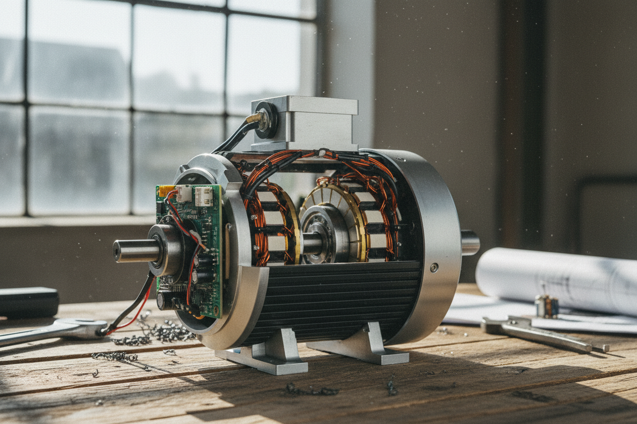
At the heart of every electric motor is a disciplined choreography between stationary and moving parts. The stator provides a structured pathway for magnetic flux, while the rotor responds to the changing magnetic field by producing torque. When current flows through stator windings, it creates a rotating field that sweeps across the air gap. Conductors in the rotor experience forces or induction of currents, following fundamental electromagnetic laws, and the mechanical output emerges as continuous rotation. Key to this conversion are the laminated steel cores that guide magnetic flux, the small but vital air gap that controls coupling, and the geometry of slots and poles that shape field distribution. The layout of windings, their pitch, and the waveform of excitation influence starting behavior, efficiency, and acoustic character. In essence, two interacting fields continually seek a lower energy state, and their alignment drives motion. This elegant principle scales from compact devices to high-power machines across the broad landscape of motors.
Inside the Stator: Structure and Windings
The stator is a precision-built magnetic circuit designed to produce a robust, well-shaped magnetic field. Its laminated core reduces eddy currents, while carefully machined slots host insulated windings that carry phase currents. Designers choose between concentrated and distributed windings to balance manufacturing simplicity, electromagnetic performance, and thermal needs. The number of poles sets the natural speed relationship, and the slot and tooth geometry tune harmonic content and torque ripple. High-quality insulation systems, resin impregnation, and tight slot fill improve reliability and thermal conduction, allowing heat to flow toward the frame and cooling paths. The housing adds mechanical stiffness and serves as a heat sink, supporting efficiency by keeping copper and iron temperatures in check. Stator design also considers stray losses, vibration, and noise, using skew, step skew, or optimized tooth shapes to smooth air-gap flux. Every dimension, from tooth width to back-iron thickness, participates in a delicate trade-off between efficiency, power density, cost, and manufacturability.
Anatomy of the Rotor: From Cages to Magnets
The rotor transforms field interaction into motion, and its design varies with motor type. In induction machines, a squirrel-cage construction uses conductive bars embedded in a laminated core and shorted by end rings; as the stator field sweeps by, induction creates rotor currents, generating torque with controllable slip. Bar shape, depth, and skew tailor starting behavior, losses, and noise. In permanent magnet machines, surface-mounted or interior magnets establish a strong rotor field, enabling high torque density and precise control, often with saliency that also leverages reluctance torque. The rotor includes a shaft, balancing features, and bearings that manage radial and axial loads, while lamination stacking reduces eddy currents and maintains efficiency. Skewing and optimized pole arc mitigate cogging torque and harmonics. Structural integrity, magnet retention, and thermal pathways are critical under high-speed or high-load operation. Ultimately, rotor geometry, materials, and cooling provisions coalesce to deliver smooth rotation, durability, and predictable electromagnetic performance.
Magnetic Fields and Torque Production
Motor action hinges on the interaction between a rotating magnetic field in the stator and the field established in the rotor. In induction designs, the difference in speed between the stator field and rotor motion, known as slip, induces currents that produce torque opposing relative motion. In synchronous and permanent magnet machines, torque arises from the angle between rotor and stator fields and may be enhanced by saliency and reluctance effects. The air-gap flux density, harmonic content, and flux path saturation profoundly influence smoothness and efficiency. Minimizing leakage flux and ensuring a uniform air gap help reduce ripple and acoustic noise. Designers tune the number of poles, winding distribution, and slot geometry to shape the rotating field, while skewing mitigates cogging and harmonic forces. Core material properties set the balance between losses and magnetic performance, and the electromagnetic layout must also respect thermal constraints, since temperature shifts affect resistance, magnet strength, and, ultimately, the motor's delivered torque.
Control, Efficiency, and Practical Performance
Modern drives elevate motor performance by shaping currents and fields with precise control. Scalar strategies like V over f provide simplicity, while field-oriented and vector control align current with the rotor field to maximize torque per ampere and dynamic response. Pulse-width modulation, smart current limits, and soft starting protect components and reduce stress. Achieving high efficiency demands attention to all losses: copper I squared R in windings, iron loss from hysteresis and eddy currents, mechanical loss from friction and windage, and stray components from harmonics. Cooling strategies range from natural convection to forced air and liquid jackets, sustaining power density and reliability. Mechanical details matter too: bearing selection, lubrication, alignment, and vibration control preserve smooth operation. Designers validate performance with thermal models, modal analysis, and electromagnetic simulation, then iterate geometry and materials to refine magnetic field quality and torque ripple. The result is a well-balanced machine that converts energy cleanly, quietly, and consistently across diverse motors applications.