Thermal Management in Motors: Cooling Methods That Work
From simple fins to liquid jackets and forced-air systems, learn how proven motor cooling methods control heat, boost efficiency, and extend life.
Foundations of Motor Heat Flow
Electric motors convert electrical energy into mechanical motion, and every conversion creates heat. The main sources are copper losses in the windings, core losses in the laminations, and mechanical losses from bearings and air friction. Left unmanaged, rising temperature increases resistance, reduces efficiency, accelerates insulation aging, and can weaken permanent magnets. Effective thermal management starts with mapping the thermal path from hot spots to ambient and minimizing thermal resistance along that route. Designers consider steady-state and transient behavior, since short bursts of load may be safe if the thermal time constant is long enough. Material choices, winding fill, slot liners, and varnish all influence how heat moves from end windings and the stator teeth to the frame. Ambient conditions, installation orientation, and enclosure style further shape temperature rise. A robust plan aligns the duty cycle, torque profile, and expected environment with a cooling method that keeps hot spots below critical thresholds and preserves long-term reliability.
Air Cooling and Surface Efficiency
Air cooling is the simplest approach, relying on conduction to the frame and natural convection to ambient. Success hinges on maximizing surface area and promoting airflow over heated surfaces without blockage. Fins increase exchange area, but their spacing, thickness, and orientation matter; closely packed fins can choke convection, while overly thick fins add mass without improving heat transfer. Vertical fin orientation can exploit the chimney effect, and smooth airflow paths reduce boundary layer buildup. Surface emissivity also contributes through radiation, which becomes more relevant at higher temperatures, so coatings that raise emissivity can help. Mounting clearance and cable routing should avoid obstructing the air path around the motor frame and end bells. Even with passive cooling, simple shrouds can guide warm air away from intakes and discourage recirculation. When natural convection is pushed to its limits, assessing temperature gradients with thermal imaging or sensors helps identify stagnant zones and fin regions needing redesign for better heat rejection.
Forced-Air Strategies That Deliver
When loads increase, forced-air cooling with fans or blowers adds controlled airflow and higher convective coefficients. Axial fans move high volume at low static pressure, ideal for open frames and straight ducts, while centrifugal blowers excel against backpressure in compact housings. Ducting and plenums should minimize sharp turns and leakage to preserve pressure and reduce noise. Filters protect windings from dust that insulates surfaces, but they must be sized for pressure drop and serviced regularly. Variable-speed fan control ties airflow to thermal demand, cutting noise and energy use at light loads while ramping aggressively as temperatures climb. Pay attention to ingress protection, as forced flow can entrain moisture or particulates; baffles and labyrinth paths help. Mechanical reliability improves with quality bearings, soft-start electronics, and redundancy for critical systems. Validate performance with temperature rise tests under worst-case ambient and altitude, since thinner air lowers cooling capacity. Properly executed, forced-air systems extend operating range without dramatically increasing motor size.
Liquid Cooling for High Power Density
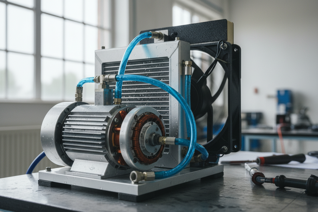
For compact, high-output motors, liquid cooling offers a major step change in heat removal. Water-glycol jackets or cold plates wrap the stator or interface with the frame, transferring heat to a loop with a pump, heat exchanger, and reservoir. Liquids have far higher thermal capacity than air, enabling tight control of winding temperatures and smaller temperature gradients across the active parts. Microchannel plates and serpentine passages boost internal convection, but they raise pressure drop, so pump selection and flow rate balance are critical. Use compatible materials and corrosion inhibitors to protect aluminum, copper, and steel, and design for galvanic isolation when dissimilar metals meet. In high-voltage settings, consider dielectric coolants or ensure robust isolation between coolant and conductors. Quick-disconnects, leak detection, and expansion management improve serviceability. While complexity and cost rise, the reward is higher power density, stable performance under sustained loads, and greater freedom to package motors in thermally challenging enclosures.
Advanced and Hybrid Cooling Techniques
Beyond air and standard jackets, advanced techniques unlock performance and reliability. Oil cooling floods or jets the end windings and rotor, directly washing heat from hotspots and damping acoustic noise; careful design maintains electrical insulation and manages oil shear losses. Jet impingement on targeted zones provides exceptional local heat transfer, often used where space is tight. Heat pipes and vapor chambers passively shuttle heat from congested cores to cooler surfaces, leveraging phase change with minimal mass. Phase-change materials buffer thermal spikes during short overloads, extending time before fans or pumps must ramp hard. Inside the motor, high-conductivity potting compounds and thermal interface materials bridge gaps between laminations, windings, and housings, reducing contact resistance while preserving dielectric strength. Hybrid systems combine these methods, such as liquid-cooled frames plus ducted air across end turns, to smooth temperature fields. Success lies in matching each technique to the motor's architecture and duty cycle, elevating both efficiency and service life.
Monitoring, Integration, and Maintenance
Even the best cooling design needs smart monitoring and thoughtful integration. Embed RTDs, NTC thermistors, or thermocouples in windings, end turns, and bearings to track true hot spots, not just frame temperature. Use model-based control to link derating and fan or pump speed to real thermal conditions, protecting insulation systems and magnets from excursions. Enclosure choices, cable glands, and mounting geometry affect airflow and coolant routing, while altitude and ambient heat lower thermal headroom; plan safety margins accordingly. Maintenance keeps performance consistent: clean fins and ducts, replace or wash filters, verify fan operation, and sample coolant for pH and inhibitor levels. Leak checks, connector inspections, and bearing temperature trends support predictive maintenance, catching issues before they escalate. Document thermal limits and train operators to recognize early signs of distress, like rising temperature gradients at steady load. With continuous feedback and disciplined care, motors maintain stable temperatures, deliver rated torque, and achieve long, reliable service.