Understanding Torque and Power: How Motors Deliver Motion
Torque makes things turn; power measures how fast work gets done. Learn how motors create both, read curves, and match specs to real-world loads.
Torque and Power Basics. Understanding how motors deliver motion starts with two foundations: torque and power. Torque is the rotational equivalent of force, the twisting action that turns shafts and wheels. Power measures how quickly work is done, representing the rate at which energy is converted into mechanical motion. In rotating systems, power scales with both torque and angular speed; increase either and you raise the output power. This relationship explains why a motor that can spin fast but produce little torque may still move light loads efficiently, while a slower motor with high torque excels at heavy lifting. It also clarifies why work, energy, and efficiency matter so much: power without sufficient torque will not overcome resistance, and torque without speed may not achieve the desired throughput. When designers think about motion, they balance torque, speed, and power to match the application's needs, always remembering that heat, friction, and losses erode what is available at the output shaft.
Where Motors Create Torque. Motors transform electrical, chemical, or fluid energy into rotational torque through force interactions. In electric machines, a stator creates a magnetic field while a rotor experiences forces from that field; the alignment and strength of the magnetic flux, plus the current flowing in windings, generate torque. Permanent magnet designs harness strong fixed fields, while induction styles induce currents in the rotor to produce motion. The interplay between applied voltage, current, and the motor's internal back EMF sets speed and torque under load. In combustion engines, expanding gases push pistons that turn a crankshaft, converting pressure into rotation. In hydraulic and pneumatic motors, pressurized fluid imparts vane or gear motion. Across technologies, the principle stays consistent: controlled energy input creates a force couple about a shaft. The specifics of materials, geometry, cooling, and magnetic circuits determine how much torque emerges, how efficiently it is produced, and how robustly it holds up under real operating conditions.
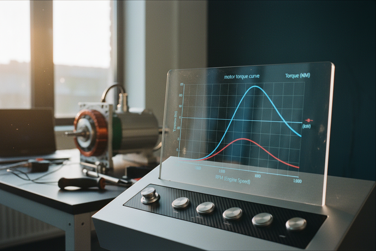
Speed, Torque, and Power Curves. Every motor exhibits characteristic speed–torque and efficiency curves that describe behavior under load. At one extreme lies stall torque, the maximum twisting effort at zero speed, while the other end is no-load speed, the fastest rotation with negligible load. Between these points, power typically peaks around mid-speed because it equals torque multiplied by angular velocity. Efficiency also varies, rising from low values at stall, peaking in a sweet spot, and falling again near no-load due to iron and friction losses. Designers use these curves to predict acceleration, steady-state speed, and thermal performance. For example, if an application demands high torque at low speed, choosing a motor optimized for that region, or pairing a motor with gearing, avoids operating far from the efficient zone. Similarly, a system needing fast response and moderate torque may favor a motor whose curve offers a wide plateau. Interpreting these profiles correctly ensures smoother starts, fewer overheating events, and a better fit between energy input and mechanical output.
Gearing and Mechanical Advantage. Motors rarely drive loads directly at their native speed; gearing reshapes the relationship between torque and rotation. A reduction gear set, belt drive, or planetary stage can multiply torque while reducing speed, trading one attribute for the other with near-conserved mechanical power minus losses. By selecting a gear ratio that places the motor in its efficient operating band, you improve response, reduce current draw, and limit heat. Mechanical advantage also helps manage inertia reflection, where the apparent inertia seen by the motor scales with the square of the gear ratio, influencing acceleration and stability. Proper gear choice dampens shocks, improves positioning precision, and extends component life. However, every transmission stage introduces friction, backlash, and potential misalignment, so precision and lubrication matter. Evaluating coupling stiffness, shaft concentricity, and load path integrity avoids resonances and vibration. The best configurations align motor characteristics, gearbox ratio, and load demands so that energy flows smoothly from electrical input to useful mechanical work.
Controlling Output for Real Work. The same motor can behave very differently under smart control. Speed, torque, and position are managed through techniques ranging from simple voltage or frequency variation to advanced vector control, field-oriented control, and pulse-width modulation. Soft-start profiles limit inrush current and reduce mechanical stress, while closed-loop feedback from encoders, resolvers, or Hall sensors provides accuracy and stability. In torque control, current is regulated to deliver a commanded twisting force regardless of speed, useful for pressing, winding, or tensioning applications. In speed control, the system adjusts voltage or frequency to maintain a target rate under changing loads. Field weakening can extend operational range at higher speeds, with careful thermal oversight. Well-tuned PID or model-based algorithms mitigate overshoot, reduce ripple, and improve dynamic response. The outcome is more reliable throughput, reduced wear, and lower energy consumption, because the motor spends more time inside its most efficient zone rather than fighting physics at the margins.
Matching a Motor to an Application. Selecting a motor is a balancing act among load profile, duty cycle, peak and continuous torque, speed range, and thermal limits. Begin by estimating inertia, friction, and external forces, then compute required acceleration and steady-state torque. Consider continuous rating for sustained tasks and ensure sufficient headroom for peaks during start, shock, or transient events. Pay attention to cooling, whether natural convection, forced air, or liquid, because heat dictates longevity and stability. Environmental factors such as dust, moisture, and temperature influence enclosure choices and insulation systems. Mechanical integration also matters: shaft type, mounting style, alignment tolerances, and allowable overhung or thrust load can make or break reliability. Electrical compatibility with available voltage, current, and control hardware ensures clean starts and predictable regulation. Finally, evaluate torque ripple, noise, and vibration if precision or comfort is important. A right-sized, well-matched motor behaves calmly, resists overloads, and translates electrical energy into motion with reassuring confidence.
Efficiency, Safety, and Longevity. High performance is hollow without efficiency and reliability. Keep bearings lubricated, belts tensioned, and couplings aligned to minimize friction and heat. Monitor winding temperatures and currents to catch overloads early; protection elements such as fuses, breakers, and thermal sensors prevent damage from faults and stalls. Clean electrical connections reduce resistance and hot spots, while balanced rotors and proper mounting cut vibration and fatigue. Where feasible, regenerative braking recovers energy during deceleration, and gentle ramp profiles reduce wear on mechanical elements. Over time, predictive maintenance using vibration, temperature, and current signatures can flag developing issues before they halt production. Documenting normal operating envelopes helps operators recognize anomalies quickly. Finally, consider system-level gains: a well-tuned controller, efficient gearing, and low-friction components cut energy use and extend service life. Treat the motor as part of an ecosystem, and the entire drive train rewards you with safer operation, lower costs, and motion that feels effortless.